
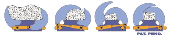
The chosen compression system must be efficient, effective and flexible.
Today the trend is to offer pre-compression boxes with swinging lids. One could say that in recent years there is no manufacturer that does not produce them, even those who once tried to discredit them.
Boxes that can be loaded from both sides, with a loading height that allows them to be fed with ordinary material handlers, while visually checking the correct distribution of the material.
The structures of the base and of the swinging lids of the pre-compression and feed boxes must be of honeycomb construction.
In particular, the honeycomb structure of the lids must be closed on the outside with a steel plate. The closed structure ensures elasticity and prevents permanent deformation caused by eccentric compression loads and torsional stresses, preferably in high-yield-strength steel to promote elastic recovery and avoid deformation from impacts.
The thickness of the wear-resistant material inside the pre-compression box, in contact with the scrap, must not be less than 30 mm.
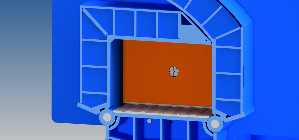
At least the sliding floor of the base must be interchangeable and made of a wear-resistant platewhich should preferably be corrugated lengthwise to prevent thin sheets from accumulating at the rear during the return stroke of the pusher and scoring the rod of the feed cylinder.
The uniformity of the longitudinal welds must be analysed: if made by submerged arc welding, they ensure consistent and uniform weld beads and high resistance to fatigue stresses.
The seats of the hinges and pivot pins of the lids must be machined once the structure is finished, and not welded onto the raw structure, perhaps with the cylinders already fitted: precise coupling is essential for a long service life of hinges, pins and cylinder rods.
Both lids of the box should have a compression overstroke to bring the material to dimensions smaller than the cross-section of the box, to make it easier to push the scrap under the shear and to significantly reduce wear; in particular, this avoids vibrations of the feed cylinder caused by the compressed scrap rubbing against the box walls.
The lack of overstroke causes wear on the inner plates in contact with the scrap, both during compression and while the compressed material slides with the box closed.
A single lid with overstroke is only half the job…
The position of the lid pivot hinges must also be checked: they must be positioned so that dust, liquids and any corrosive materials do not settle on the rods during scrap compression, damaging the wiper and the chrome plating.
In practice, one of the hinges welded to the base must be positioned above the rod of the lid cylinders.
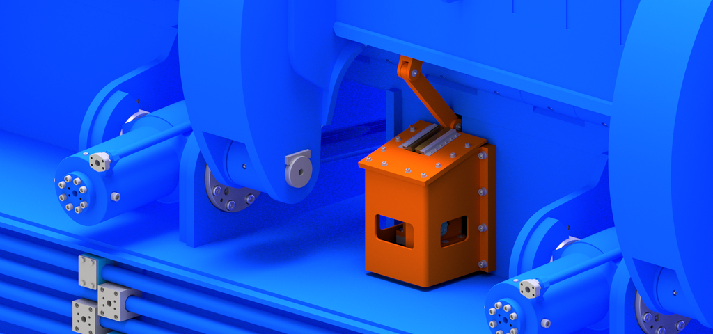
The position of the lids should preferably be controlled by rotary or linear encoders; the use of toggle control with an encoder outside the cylinders is an interesting option..
A protected encoder outside the cylinders avoids the use of mechanical limit switches, proximity switches and linear sensors inside the cylinders, which are easily damaged and difficult to replace and maintain.
The device controls the overstroke and checks the correct position of the lids with the box closed.
The smooth, shock-free movement of the lids, both when opening and closing, can be obtained with rotary or linear encoders that communicate, through a proper working program, with devices on the directional valves and mechanical brakes built into the cylinder bottoms… all strictly together!
The cylinders that drive the lids must be located under the box and not outside it, so that they are protected from falling scrap during loading.
It must be checked that the lid cylinders are positioned so as to optimise the transmission of the compression force and develop maximum torque when maximum effort is needed.
Make sure that the machine is supplied with guards for the lid cylinders and their hoses.
The cross-section of the box, the loading capacity and the compression force of the lids must be matched to the cutting force.
There is no point in having a 1000 tons shear if the pre-compression box cannot crush the scrap for which that cutting force is intended. Experience recommends the following cutting section dimensions: 600x800 mm up to 600 tons of cutting force; 600x900 mm from 600 to 800 tons of cutting force; 700x1000 mm from 1000 to 1200 tons of cutting force; 800x1100 mm from 1200 to 1500 tons of cutting force.
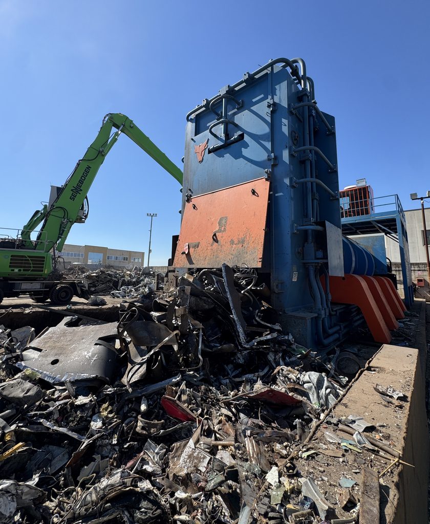
Among the factors that condition and limit the productivity of shear balers, great attention must be paid to the time the operator takes to prepare the scrap before pressing “start” on the automatic shearing cycle.
It is therefore not enough to assess shear balers for their solidity and robustness: they must also be assessed for their productivity which, among other parameters, depends on the ability of the pre-compression system to adapt to different types of scrap with alternating, independent and successive movements of the lids.
The open feed box must have a large capacity, allowing larger quantities of scrap to be prepared inside it for pre-compression with each load.
The supply of a side pre-loading system should be considered, to significantly reduce feeding downtime and increase productivity. The pre-loading tray must strictly be made of high-strength wear-resistant steel to avoid deformation caused by the inevitable impacts during loading.
The double-acting cylinders that control the tilting stroke must be braked at the end of stroke and fitted with rotary or linear encoders to control position, soften movements and avoid impacts, both when opening and closing.
Eng. CLAUDIO COLOMBO