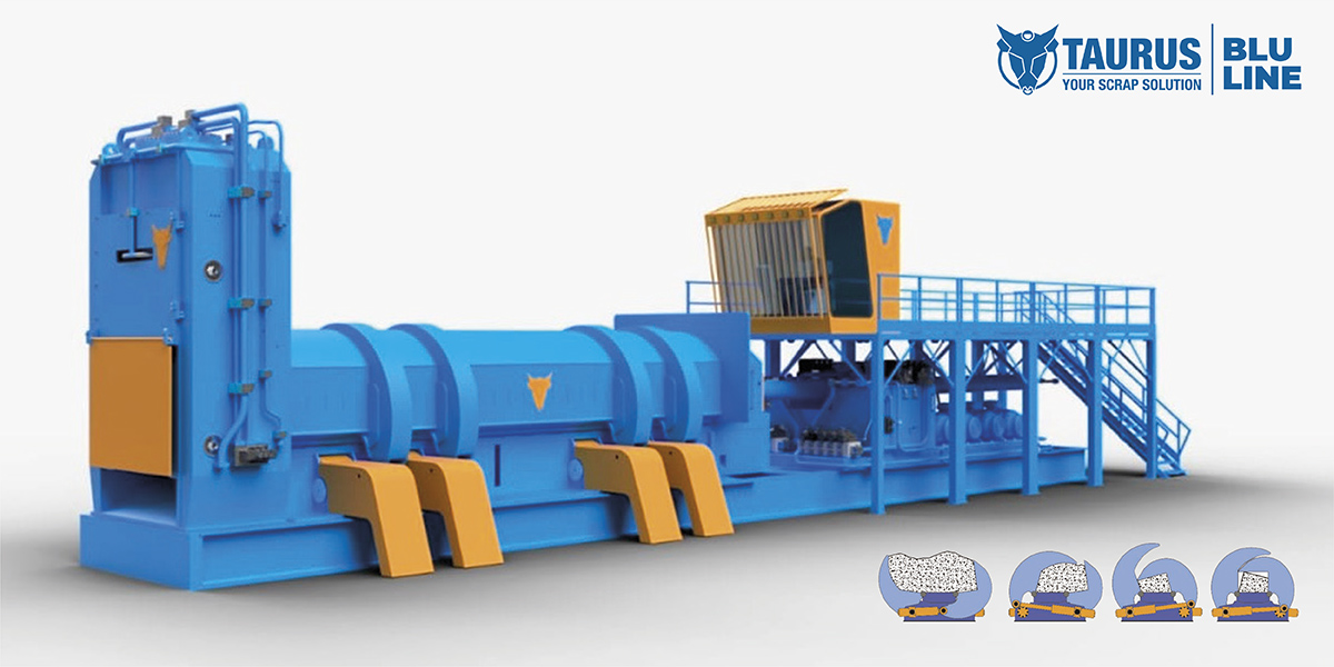
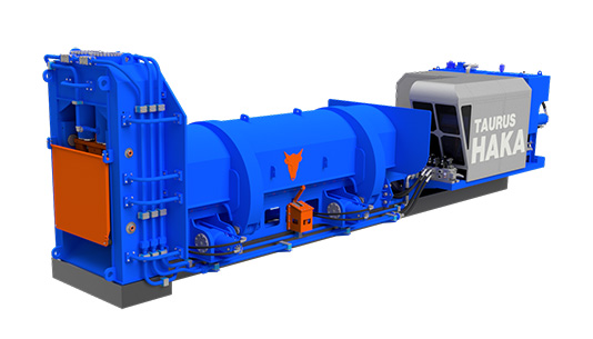
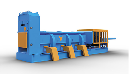
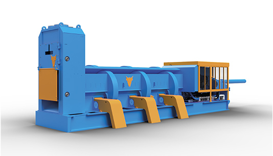
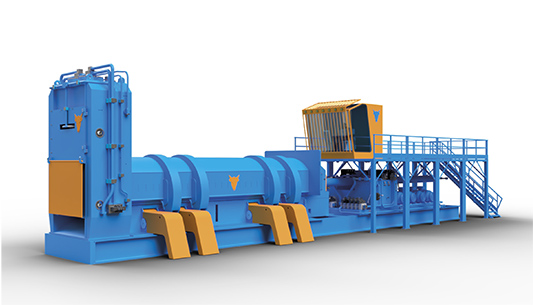
STATIONARY SHEAR BALER
STATIONARY SHEAR BALER, TOP OF THE RANGE
The purpose of shear balers is simple: to cut scrap
metal into sizes and densities that optimize storage
space, reduce loading times, cut transport costs, and
provide scrap that is ‘furnace ready ’. The challenge
lies in building a machine that represents the very
best in engineering and technology.
The TECHNIQUE is our know-how, our ability to design
and build by applying the knowledge gained through
experience, having thoroughly analyzed
The TECHNOLOGIES are our approach to innovation and research; they are the application of processes and solutions that require advanced technical.
TECHNIQUE AND TECHNOLOGY applied to the study and development of ever-new ideas.
The scrap market is undergoing radical changes to which the scrap and machinery industries must adapt. Today, a shear baler is not chosen solely on the basis of its productivity but also, and above all, for its versatility, operating costs, auxiliary facility costs, foundation costs, ease of relocation, ease of maintenance, safety, and, above all, as an amortizable investment that pays for itself quickly
All of this is Qthe shear baler designed for the future. A large‑scale machine designed for high‑level performance, born after more than 60 years during which we have invested, experimented, engineered, and devoted ourselves solely to the the construction and development of scrap shears.
Q: the synthesis of our work and our experience.

FEATURES
STRUCTURE
- Box and wings featuring a sandwich structure with reticulated core, designed to increase bending and torsional stiffness
- The surfaces in direct contact with the scrap, as well as the inner and outer surfaces of the lids, are made of wear‑resistant steel
- Support frame with leachate collection tank
- THE MACHINE DOES NOT REQUIRE FOUNDATIONS
ELECTRONICS SYSTEM
- CSA: end‑of‑stroke decelerators
- EPS: non‑contact stroke limiters
- ECA: stroke economizer
- KNEE (Patented): Angular sensor for monitoring the lids’ over‑stroke
- IDS: inductive end‑of‑stroke sensors
- HP: work‑cycle economizer
- BOOSTER
- Remote diagnostics and remote technical assistance
- Double‑enclosure electrical cabinet
- Touch screen
- Remote control
HIDRAULIC UNIT
- Axial piston pumps with working pressures up to 420 bar
- Oil filtration and cooling pump
- Piloting pump
- Steel distribution panels
- CETOP‑standard valves
- Proportional valves
- SIR: integrated fast/slow cycle system
- Logic‑element panel
- BOOSTER
- Air filters
- Oil filtration performed on an independent external circuit
- Pilot line filter
- Air‑oil cooling
- LCC: centralized shear lubrication system
ON DEMAND
- Self‑supporting loading hopper without external auxiliary support structures
- Support frame with anti‑vibration system
- LM: air‑conditioned operator cabin
- TER: pre‑compression monitoring system
- LAC: automatic hinge lubrication
- LAS: automatic lubrication of the cylinder‑lid joint
- Oil heating system
TECHNICAL SPECIFICATIONS
| Cutting force | up to T 1500 |
| Clamp | up to T 400 |
| Main compression cylinder | up to T 180 |
| Box length | up to mm 8300 |
| Motorization | Electric or Diesel |