Similar design solutions, yet fundamentally different in the way they operate.
In a guillotine shear, the moving blade holder must descend with precision while maintaining a constant clearance between the moving and fixed blades. The guide system therefore plays a critical role: it prevents the blade holder from tilting, moving laterally, or pulling away from the fixed blade during the cutting process.
Two guide system solutions are commonly adopted:
- the prismatic guide system, featuring three guiding surfaces on each side;
- the simplified guide system, featuring one flat rear guide and one inclined front guide on each side.
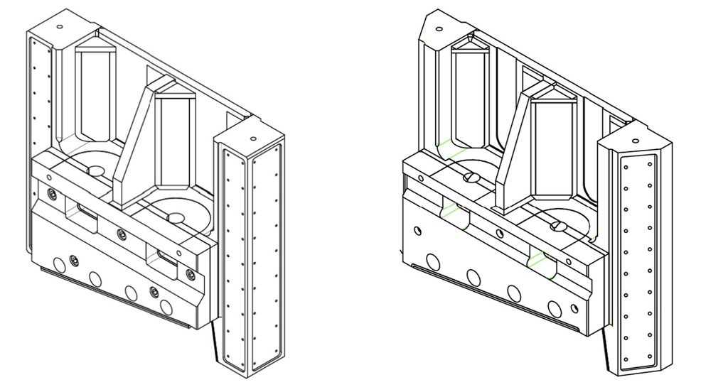
The second solution uses fewer components, but it is not necessarily simpler in terms of operation, design, or maintenance.
Forces Acting on the Blade Holder
During the cutting process, the blade holder is not subjected solely to the vertical force required to shear the material; several other forces are also generated:
- a transverse force that tends to push the moving blade away from the fixed blade;
- a lateral force, primarily generated by the inclination of the blade;
- a moment generated by the offset between the cutting force and the reaction force exerted by the material;
- an additional moment is generated when the cut is performed away from the centerline of the blade.
diminuiscono in altre. These moments tend to tilt or twist the blade holder. As a result, the pressure distribution on the guides is no longer uniform: it increases in some areas and decreases in others.
In the most severe loading conditions, one guide may become heavily loaded while another may lose contact altogether.
The Three-Prismatic-Guide System on Each Side
In the prismatic guide system, each side of the blade holder typically incorporates:
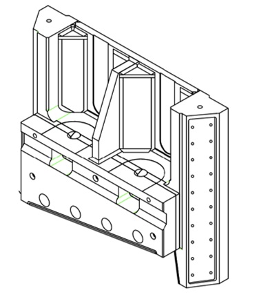
- a front guide surface;
- a rear guide surface;
- a lateral guide surface.
The front and rear guide surfaces primarily counteract the forces that tend to separate the moving and fixed blades, as well as the moments that cause the blade holder to tilt.
The lateral guide surface, on the other hand, counteracts the force pushing the blade holder toward the shear side frame, as well as the effects generated by off-center cutting.
The primary advantage of this arrangement lies in the separation of functions: each set of guide surfaces operates predominantly in the direction for which it was specifically designed.
This simplifies:
- understanding the force path;
- pressure calculation;
- adjustment of clearances;
- wear monitoring;
- identifying the causes of any misalignment.
However, this system involves a greater number of machined surfaces and can potentially be statically indeterminate. This means that if too many surfaces are adjusted simultaneously without sufficient precision, the load may be distributed differently from the intended design.
The guides are sliding contact surfaces that can transmit compressive forces but not tensile forces. Overconstraint arises when multiple contact surfaces are simultaneously engaged.
The system with two guides per side
The alternative solution eliminates the dedicated side guide.
Each side features:
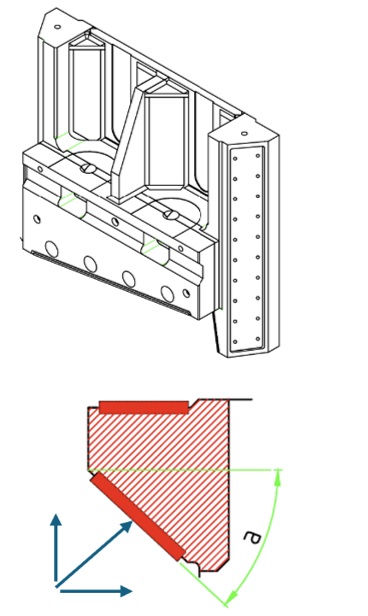
- a flat rear guide surface
- an inclined front guide
The inclined guide must perform two functions simultaneously.
- counteract the transverse force that tends to push the blades apart.
- counteract the lateral force directed toward the shoulder.
Neglecting friction, the reaction force generated by the guide is always perpendicular to its surface. Because the guide is inclined, this reaction force automatically includes both a transverse component and a lateral component.
The two load directions are therefore coupled.
When the lateral force increases, the transverse load changes as well. Likewise, any variation in the transverse load alters the lateral component generated by the inclined guide.
The two load directions are therefore coupled.
The Importance of the Angle
The angle of the inclined guide determines how effectively it can counteract the two load directions.
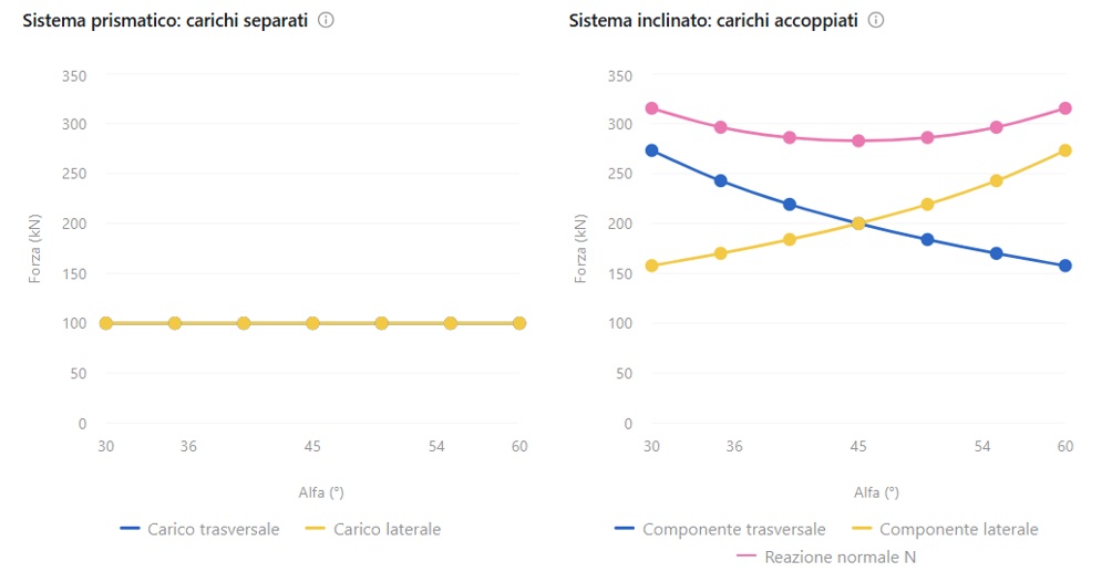
For example, with a 30° angle, a normal reaction force of approximately 200 kN is required at the guide to obtain a lateral component of 100 kN. The same reaction force also generates a transverse component of approximately 173 kN.
In the prismatic system, by contrast, the lateral guide would directly carry the 100 kN load without automatically generating that additional transverse load.
A small angle therefore makes the inclined guide less effective in the lateral direction and increases:
- the normal reaction force
- the contact pressure
- the load on the gib
- the load on the adjustment devices
- the risk of unloading the rear guide
As the angle increases, the transverse component generated by the lateral load decreases, while the lateral component generated by the transverse load increases. Consequently, there is no angle that eliminates the coupling between the two load directions; only the ratio between the two components changes.
Possible unloading of the rear guide
The inclined guide also helps counteract the force that tends to push the blades apart. As a result, the rear guide only has to carry the remaining load.
This may appear advantageous, but there is an important limitation: a contact guide can push, but it cannot pull.
If the transverse component generated by the inclined guide exceeds the load to be balanced, the calculation would require a negative reaction force at the rear guide. Physically, this means that the rear guide loses contact.
From that point onward, the force distribution changes completely, and the analysis must be repeated considering only the contact surfaces that remain active.
Machining operations
The two-guide system eliminates one lateral guide surface and may therefore appear to require less machining and, consequently, lower manufacturing costs than the prismatic guide system. However, it introduces a different challenge.
The inclined guide of the blade holder and its mating guide must have:
- the same angle;
- high flatness;
- high parallelism
- consistent positioning on both side frames
- sufficient stiffness to limit deformation
It is not sufficient to check only the assembly clearance. Even a small angular error results in a variation of the clearance along the height of the guide.
In the prismatic system, the guide surfaces are generally orthogonal, and the different load directions can be machined and inspected independently. Although the number of surfaces is greater, their geometry is simpler.
Adjustment and wear
In the prismatic system, wear of the lateral guide can be compensated for without directly affecting the adjustment of the front and rear guides.
In the inclined-guide system, by contrast, adjusting a gib affects the following simultaneously:
- the transverse clearance;
- the lateral alignment;
- the pressure on the rear guide;
- the position of the blade holder relative to the blades.
If wear is not uniform, simply tightening the gib may not be sufficient. It may be necessary to restore the original guide angle, regrind the guide surfaces, or replace the guide and mating guide as a matched pair.
Differences in guide angle, structural deformation, contamination, or excessive adjustment can also promote wedge-like behaviour. The inclination does not automatically cause jamming, but it does make the system more sensitive to geometric inaccuracies and wear.
On-site maintenance
The difference between the two systems becomes particularly evident when all guides need to be replaced with the shear still installed, for example at a job site where the available lifting and handling equipment may not be suitable, making the intervention more complex.
When the inclined guides and the blade holder are removed, the following are simultaneously lost:
- the transverse reference;
- the lateral alignment;
- the angular position;
- the geometric relationship with the fixed blade.
Reassembly therefore requires independent and permanent reference features, such as machined surfaces, dowel pins, keys, calibrated shims, and alignment fixtures.
In the prismatic system, the separation of functions makes it easier to carry out a progressive replacement and to perform adjustments one direction at a time. In this case as well, the blade holder must be supported using properly designed and certified equipment; however, the geometry is generally easier to re-establish.
Which system is better?
The inclined guide is not an inherently flawed solution. It can be an effective choice when:
- the contact surfaces are large;
- le superfici di contatto sono ampie;
- the structure is highly rigid;
- the guide angles are machined accurately;
- clearances and preloads are properly controlled;
- maintenance personnel have access to suitable reference features and alignment tools.
The prismatic system requires more guide surfaces and careful adjustment, but it provides a clearer separation of functions and a more predictable response under varying load conditions.
For a heavy-duty shear intended for scrap processing, where off-center cuts, impacts, wear, and challenging maintenance conditions are common, the prismatic system generally offers greater robustness, easier interpretation of machine behaviour, and simpler restoration procedures.
The inclined-guide solution is more compact, but the reduction in the number of guide surfaces comes at the cost of increased complexity in force transmission, machining, adjustment, and maintenance.
In conclusion, the choice should not be based solely on the number of components. Having one less guide does not necessarily result in a simpler machine; in some cases, it means concentrating on a single surface functions that, in the prismatic system, remain clearly separated.
Advantages and Disadvantages
ASPECT
PRISMATIC GUIDES
INCLINED GUIDES
Load separation
Fs and Fl absorbed by different guides
Loads coupled on the same guide
Reaction for a given
Equal to the lateral load
Amplificata di 1/ sin α
Transverse component generated by Fl
Practically absent
Pari a Fl cot α
Load on the eccentric pins
More directly predictable
Depends on the combination of the two loads
Adjustment
Separate in the two directions
One adjustment affects both directions
Machining
One additional lateral guide surface
Fewer surfaces, but angle and parallelism are more critical
Wear
Easier to compensate independently
Can simultaneously affect transverse and lateral clearances
Risk of loss of contact
Easier to control
Higher due to load coupling
Pressure on the lateral/incl
Lower for the same contact area
More compact, but more sensitive to operating and maintenance conditions