
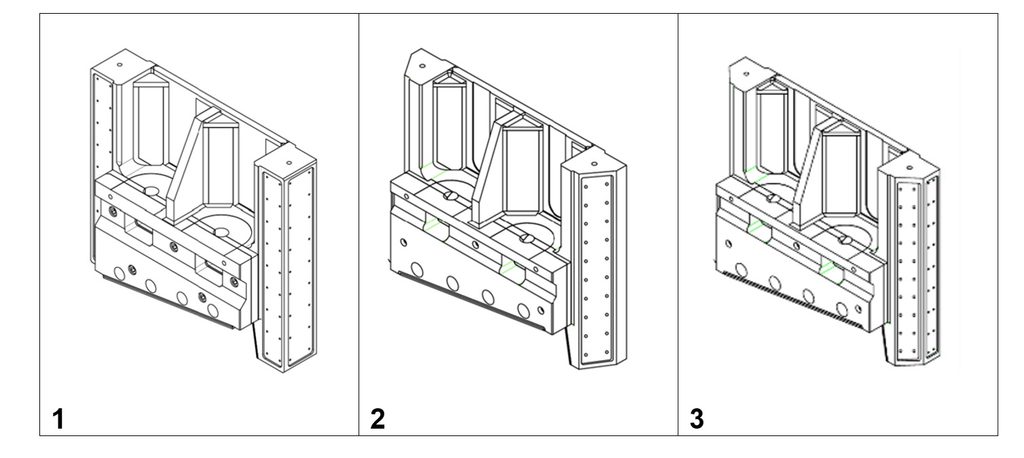
Three Guide Systems compared
- Three orthogonal guides per side
- Two guides per side: one flat rear guide and one inclined front guide.
- Three guides on each side: one flat rear guide, one inclined front guide, and one flat lateral guide.
1. Three orthogonal guides per side
Each side of the blade holder is equipped with:
- Flat front guide
- Flat rear guide
- Flat lateral guide.
The functions are separated:
- the front and rear guides oppose the force that tends to separate the blades;
- the lateral guide opposes movement toward the side frame;
- The resulting moments alter the pressure distribution along the guides and between the two side frames.
Advantages
- Transverse and lateral loads are clearly separated,
- More predictable behavior,
- Adjustments are relatively independent,
- Lateral wear is independent of transverse wear,
- It is easier to identify which guide is overloaded,
- Maintenance and alignment are easier to understand and perform,
- No sensitivity to angular misalignment,
- Loads acting on the adjustment systems can be determined more easily.
Disadvantages
- A greater number of orthogonal surfaces must be machined,
- More gibs and adjustment components are required,
- Potential for hyperstaticity,
- Accurate alignment between the two side frames is still required.
2. Due guide per lato, una delle quali inclinata
Each side features:
- Flat rear guide
- rear inclined guide
There is no dedicated lateral guide.
The inclined guide is therefore required to simultaneously resist:
- the transverse force;
- the lateral force;
- part of the effects generated by the moments.
Its normal reaction force (N) generates:
T = N cos α , acting in the transverse direction;
L = N sin α, acting in the lateral direction.
Advantages
- Fewer surfaces
- More compact structure,
- Fewer guides
- The two inclined guides can provide lateral centering of the blade carrier
Disadvantages
- The inclined guide must withstand loads in both directions
- High normal load on the inclined surface
- Strong coupling between transverse adjustment and lateral behavior
- No dedicated independent lateral guide
.
- Greater sensitivity to uneven wear
- Greater sensitivity to angular and parallelism errors
- One of the two inclined guides may become unloaded
- Possible load concentration on a single side frame
- More difficult maintenance and centering procedures
- If one guide loses contact, the other may have to carry most of the lateral load.
With α =30° if a single inclined guide must resist the lateral load:

N = 2FL The normal reaction force may therefore be significantly greater than the required lateral force.
3. Mixed system: three guides per side, one of which is inclined
Each side features:
- Flat rear guide
- Front inclined guide
- Flat lateral guide.
This solution retains the lateral guide, but the inclined guide also generates a lateral component
When all surfaces are in contact

The lateral load is therefore shared between:
- Flat lateral guides
- lateral components generated by the inclined guides
Advantages
- Presence of a dedicated lateral guide,
- High stiffness when all surfaces are correctly adjusted and in contact,
- The inclined guides can contribute to centering the blade carrier,
- Greater overall capacity to resist displacement.
Disadvantages
- Does not reduce the number of surfaces,
- Requires both lateral and inclined machining operations,
- The inclined guide and the lateral guide oppose the same movement,
- A highly hyperstatic system when all contacts are active,
- Load distribution depends on clearances, stiffnesses, and wear conditions,
- Adjustment of the inclined guides does not eliminate clearance in the lateral guides,
- The inclined guides may become the effective lateral reference,
- Worn lateral guides may remain inactive,
- The lateral guides may suddenly come back into contact,
- Diagnosis and maintenance are more complex.
Effect of Wear in the Third System
Adjustment of the inclined guides takes place in the direction of the transverse force. It does not directly move the lateral gibs and therefore does not eliminate clearance in the lateral guides.
However, by symmetrically adjusting the two inclined guides, the blade carrier is re-centered between them.
If the lateral guides are worn:
- the blade carrier may remain detached from the lateral guides;
- the inclined guides become the primary lateral constraint;
- one inclined guide becomes loaded while the opposite guide is unloaded;
- the lateral load may be carried almost entirely by the inclined guides.
The lateral guides become active again only after the blade carrier has moved through their remaining clearance.
Summary Table
FEATURE
THREE ORTHOGONAL GUIDES
TWO GUIDES, ONE INCLINED
MIXED SYSTEM
Guides per side
3
2
3
Dedicated lateral guide
Yes
No
Yes
Load separation
Good
None
Partial
Transverse load
Front and rear guides
Rear and inclined guides
Rear and inclined guides
Lateral load
Lateral guide
Inclined guides
Lateral and inclined guides
Load coupling
Limited
Very High
High
Lateral centering
Lateral guide
Inclined guides
Inclined or lateral guides, depending on contact conditions
Hyperstaticity
Possible, but more separated
Depends on contact conditions
Significant when all guides are active
Angular accuracy requirement
Not critical
Essential
Essential
Number of machining operations
Higher
Lower
Not lower than the orthogonal system
Adjustment
More independent
Strongly coupled
Coordinated between lateral and inclined guides
Effect of lateral wear
Effect of
Directly affects centering
May exclude the lateral guides from carrying the load
Overloading
None
Likely under severe operating conditions
Possible when the lateral guides are worn
Contact engagement
More predictable
Depends on clearances
May occur in multiple stages
Ease of calculation
Higher
Lower
Lower
Ease of diagnosis
Higher
Lower
Most complex
Maintenance
Simpler
Demanding
Very demanding
Suitability for off-center loads
Good
Good stiffness but uncertain load distribution
Good stiffness but uncertain load distribution
Final Evaluation
Orthogonal System
This is generally the simplest, most predictable, and easiest solution to restore and maintain. The separation of functions allows transverse and lateral clearances to be measured and corrected independently.
It is the solution that provides the clearest behavior in the presence of:
- off-center cutting;
- non-uniform wear;
- shock loads;
- field maintenance operations;
- long-term service over many years.
Two-Guide System
This is the most compact solution, but it relies on the inclined guides for both transverse and lateral centering.
It can perform satisfactorily when:
- the contact surfaces are large;
- the bearing surfaces are sufficiently extensive;
- the geometry is highly accurate;
- maintenance is performed regularly;
- wear is effectively controlled.
However, this is also the system in which the inclined guide is subjected to the highest loads.
Mixed System with Lateral and Inclined Guides
This configuration is potentially the stiffest when new and perfectly adjusted. However, it is also the most complex in terms of actual load distribution.
As wear progresses, the inclined guides may center the blade carrier while leaving the lateral guides inactive. When the lateral guides eventually come back into contact, the system becomes highly overconstrained, and the load distribution can no longer be predicted by statics alone.
Conclusion
For a heavy-duty shear intended to operate under severe working conditions, the generally preferred solution is:
THREE ORTHOGONAL GUIDES PER SIDE
The two-guide system is simpler in terms of component count, but it concentrates more functions and higher loads on the inclined surfaces.
The mixed system can provide high stiffness, but it requires the most careful control of:
- angles;
- clearances;
- wear;
- contact sequence;
- lateral guide adjustment;
- load distribution between the two side frames
Ranking by Predictability and Ease of Maintenance
- Three orthogonal guides
- Two guides, one inclined
- Mixed system
Ranking by Load Distribution Complexity
- Mixed system
- Two guides, one inclined
- Three orthogonal guides